This document is not up-to-date, please refer to the Japanese document.
RAVEN HardWare Specification
Detailed hardware information about RAVEN.
Table of Contents
Features
- STM32F767 MCU( Cortex®-M7@216MHz, 2MB Flash, 512KB SRAM )
- 64Mbit SPI Serial Flash
- WLAN module( 802.11 b/g/n )
- User defined LED and Switch
- DAPLink interface
- Drag-and-drop programming
- USB Virtual COM Port
- CMSIS-DAP Debugger
- Four Multi-function I/O Connectors
- Compatible with 3.3V sensor and actuators
- Multiple peripheral functions( ADC/UART/I2C/PWM )
- Each port is capable of supplying up to 50 mA
General Specifications
- Dimensions
- 75mm x 35mm x 12mm( WxDxH )( excluding projections )
- Rating
- Approx. 5V/2.5W( Power Supply : via micro-USB terminal )
- Weight
- Approx. 22g
Technical Specifications
Please refer to the charts below for the ratings and the specifications of the unit.
Absolute maximum ratings
| Ratings | Symbol | Min | Max | Unit | Comment |
|---|---|---|---|---|---|
| Power supply voltage | VBUS | -0.3 | 5.5 | V | - |
| Input voltage(PORT) | VIO | -0.3 | 7.0 | V | Excluding "+3.3V OUT" Pin |
| Input voltage(USB) | VUSBIO | -0.5 | 3.6 | V | VBUS=0V |
| Operating temperature | Topr | -20 | 70 | deg.C | No condensation |
General operating conditions
| Ratings | Symbol | Min | Max | Unit | Comment |
|---|---|---|---|---|---|
| Standard operating voltage | VBUS | 3.0 | 5.25 | V | - |
| Operating temperature range | Ta | 0 | 40 | deg.C | No condensation |
| Operating humidity range | RH | 20 | 80 | % | - |
Electrical characteristics
| Ratings | Symbol | Min | Max | Unit | Comment |
|---|---|---|---|---|---|
| Output voltage(Power pin) | VO | 3.1 | 3.45 | V | TYP=3.3V |
| Output current(Power pin) | IO | - | 200 | mA | 4ports total |
| High-level output voltage(I/O pin) | VOH | VO-0.4 | VO | V | IIO = -8mA |
| Low-level output voltage(I/O pin) | VOL | 0 | 0.4 | V | IIO = 8mA |
| High-level input voltage(I/O pin) | VIH | 0.7*VO | VO | V | - |
| Low-level input voltage(I/O pin) | VIL | 0 | 0.3*VO | V | - |
| leakage current(I/O pin) | Ilkg | - | 3 | uA | 5V,Input,Disable PU/PD |
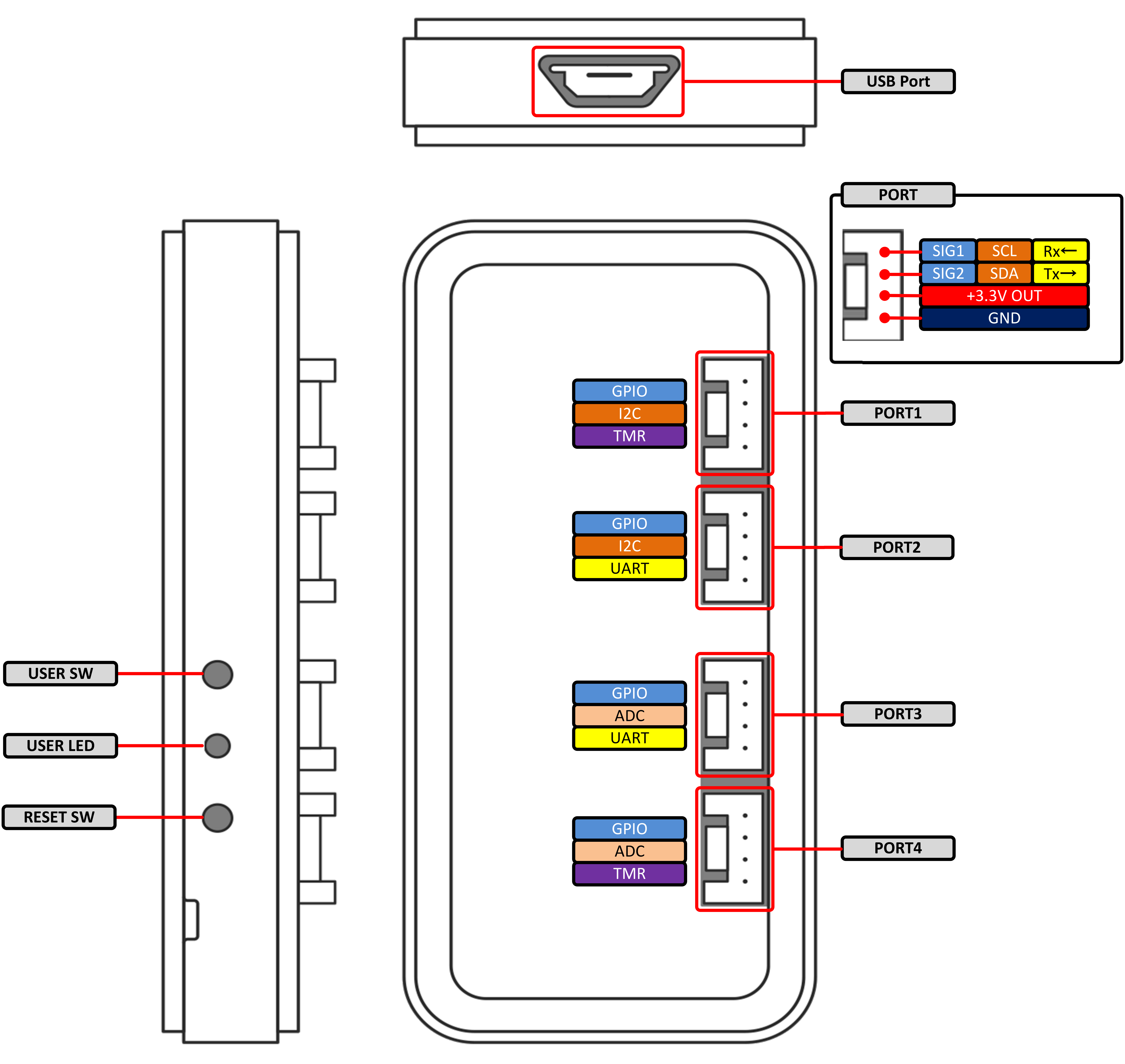
Notes on the Ports
- I/O connectors can be configured to assign different functions by flow settings, and therefore these are defined as "Ports" in this documentation.
- The Ports operate at 3.3V. Sensors/actuators which are specifically designed for 5V operation are not compatible with this unit.
- The Ports are not designed to be disconnected while in operation(they do not support "hot swapping"). Please remember to turn the power off before connecting to or disconnecting sensors/actuators from the Ports.
- The maximum current for each Port is rated at 50mA(the total current of 4 Ports at 200mA). Please pay attention not to exceed these limitations.
- Do not feed power into the power terminals of the Ports. Such an action can cause damages on the unit.
- The power supply of sensors/actuators cannot be controlled from Flows (RAVEN constantly supplies power to these Ports).
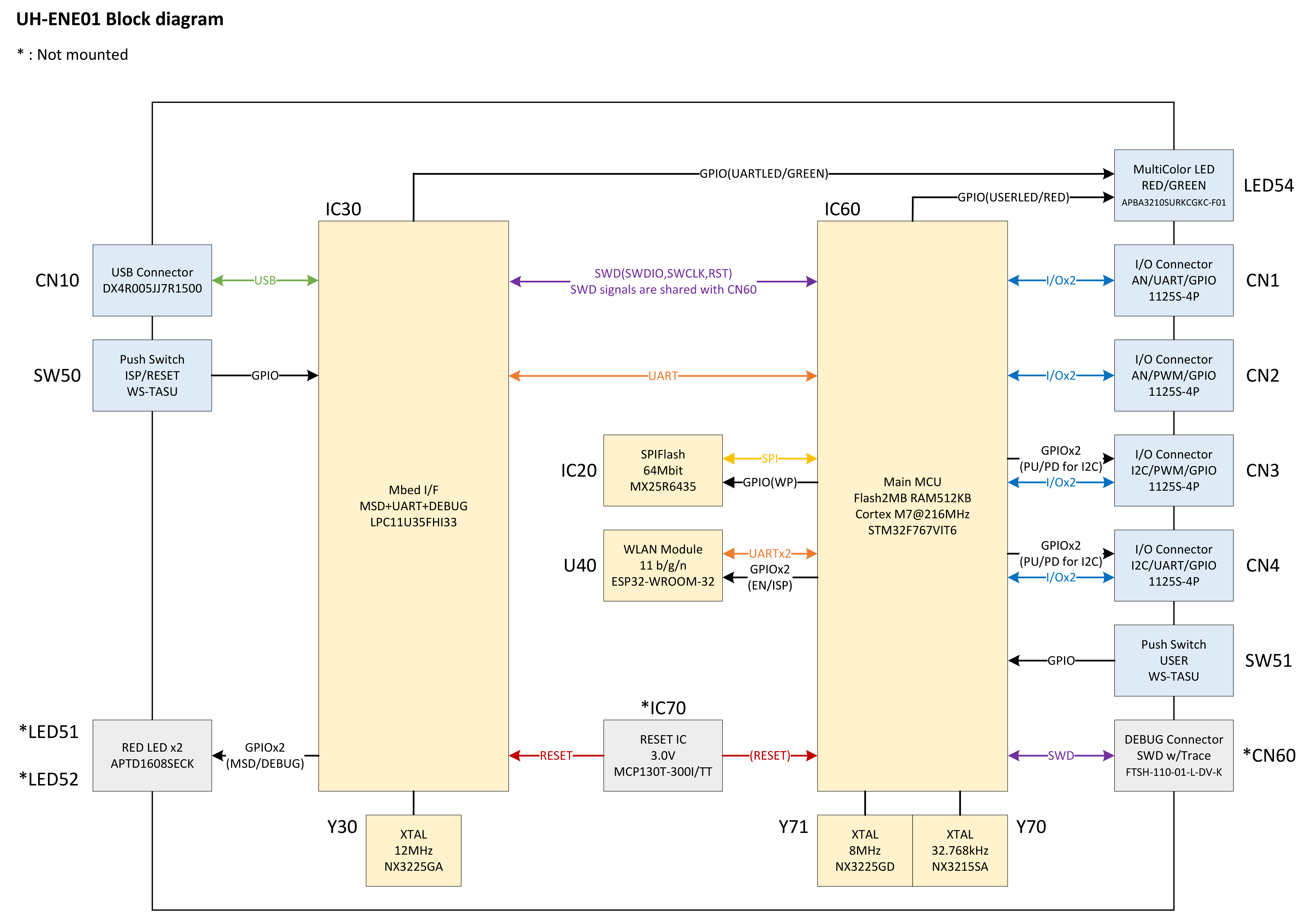
Signal pins(SIG1/2) on the Ports 1-4 are connected through the protective registers (33ohms). When a Port is active, its function, I/O and its pull up/down state are defined within the flow. At the power-on state(before flows are read into internal firmware), all Ports are disabled.
- PORT3/4
- When these ports are disabled, they are configured as input ports and are pulled-down by MCU approximatelly at 40 kilo-ohms.
- PORT1/2
- When these ports are disabled, they are configured as input ports and are pulled-up by MCU approximatelly at 4.7 kilo-ohms.
- When these ports operate as I2C or SDL/SDA lines are pulled-up at 4.7 kilo-ohms.
- PORT3/4
There are limitations to the functions each Port can be configured to.
Please refer to the diagram for the details.
NOTE: The diagram mentions PWM(TMR) and UART, however these features have yet been implemented.
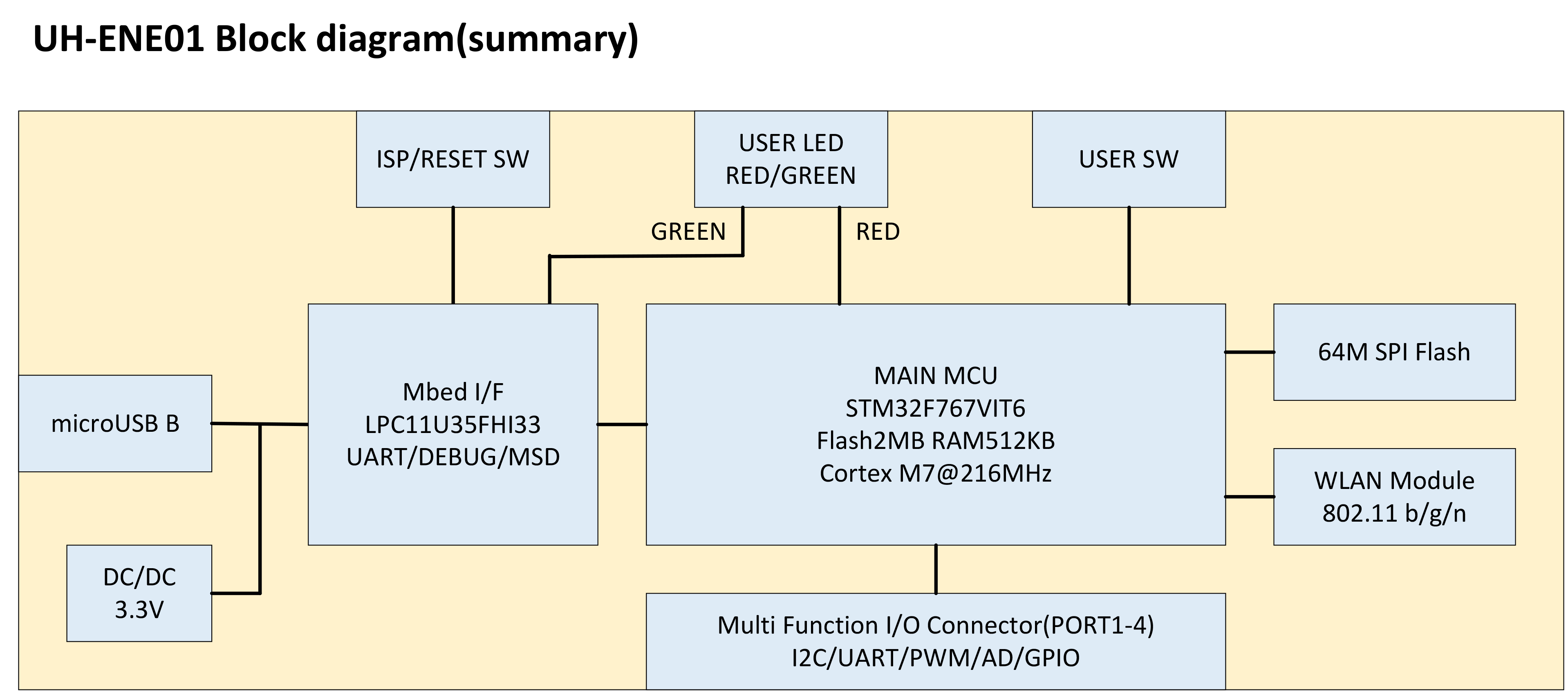
Notes on the Internal function block
- SPIFlash, WLAN module, MbedI/F(DAPLink), the Ports, the user switch, and the user LED are connected around main MCU(STM32F767).
- The SPIFlash is reserved by the system and currently cannot be accessed from flows.
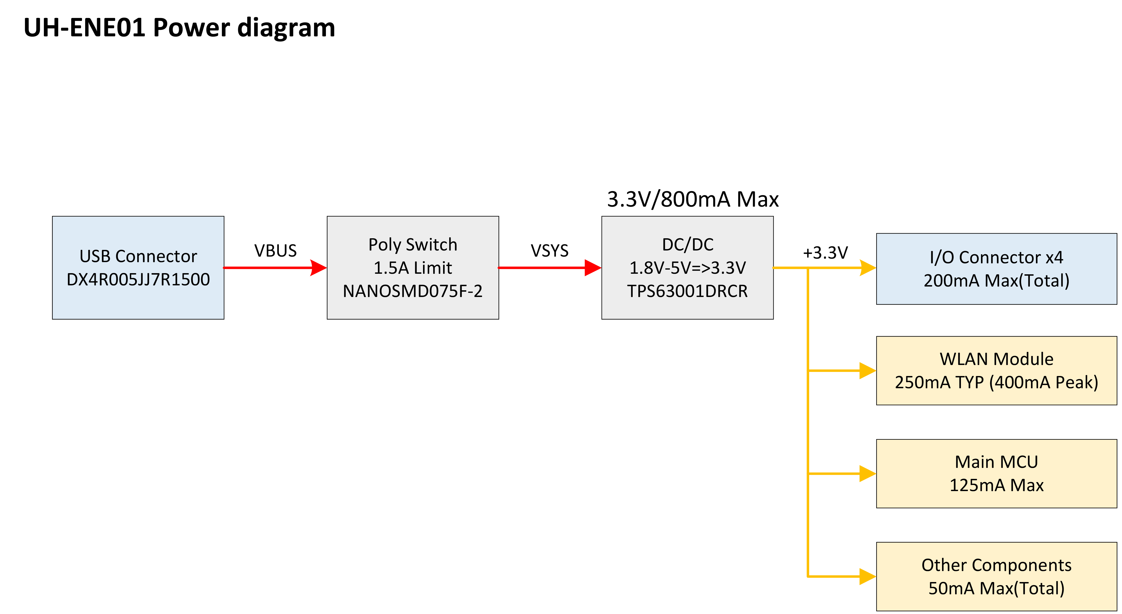
Notes on the Internal Power block
- The input voltage which is fed through the microUSB connector is conveted into 3.3V by the Buck-Boost regulator, then supplied to internal circuitry and Ports.
- The internal power block is protected by a Poly Switch directly next to the USB line and the built-in protection of the Buck-Boost regulator.